
Mining and Geotechnical Vibration and Deep Displacement Monitoring
A mining and geotechnical monitoring case group covering ground vibration monitoring, post-blasting deformation monitoring, slope movement, tailings or open-pit risk, and borehole deep displacement monitoring.
Project Type
Civil Infrastructure Structural Monitoring
System Scale
ground vibration monitoring points, slope deformation stations, and borehole displacement arrays
Data Output
ground vibration time history, peak vibration, slope displacement, tilt, borehole deep displacement, and trend alarms
Engineering Value
How the system supported engineering decisions
The case extends DL monitoring from civil structures into mining slope, post-blasting deformation, ground vibration, and subsurface displacement applications.
Event capture and long-term deformation monitoring are presented as one geotechnical risk workflow.
Borehole deep displacement monitoring strengthens the site's capability language for mining and slope projects.
Monitoring Content
Monitoring scope and field constraints addressed by the deployment
Ground vibration monitoring needed reliable event capture and threshold review near sensitive structures or mine slopes.
Slope and tailings safety required long-term displacement and deformation trends rather than one-time inspection.
Borehole arrays needed depth-based movement evidence for geotechnical risk interpretation.
System Configuration
Configured system architecture and data path
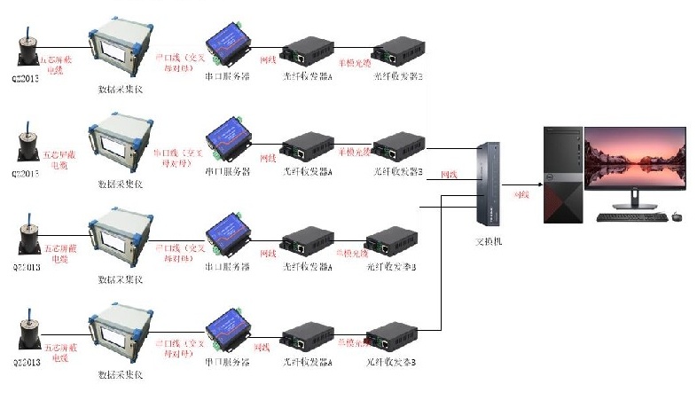
Field Devices
DL-VIB ground vibration instruments, DL-GN displacement stations, DL-SEN tilt or deep displacement points, and protected field cabinets
Communication Layer
Field event capture and remote transmission through wired, 4G, or site network links
Central Platform
DL monitoring platform for event review, deformation trend display, threshold alarms, and geotechnical reporting
Case Visual Evidence
Source visuals and deployment references
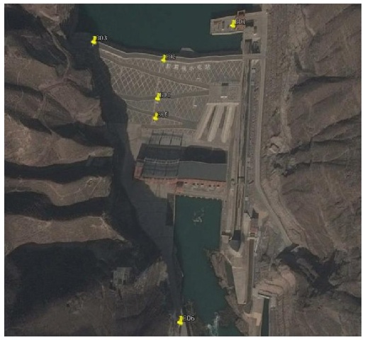
Slope and dam-zone monitoring point reference
Marked field points show how vibration or deformation stations can be arranged around slope, dam, or open-pit risk areas.
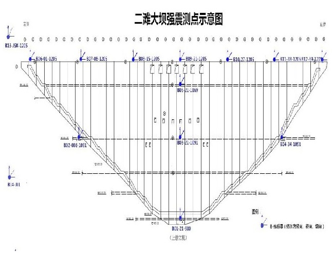
Measuring point layout diagram
Cross-section layout evidence supports crest, slope, foundation, and free-field point planning for geotechnical safety monitoring.
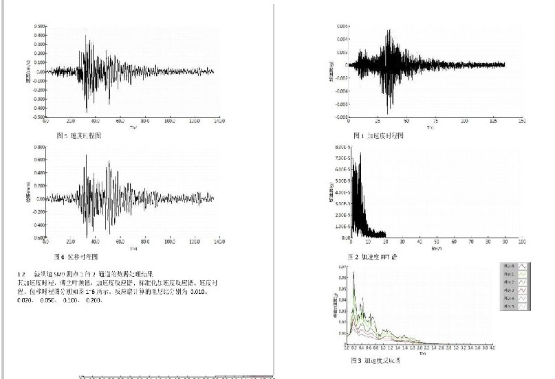
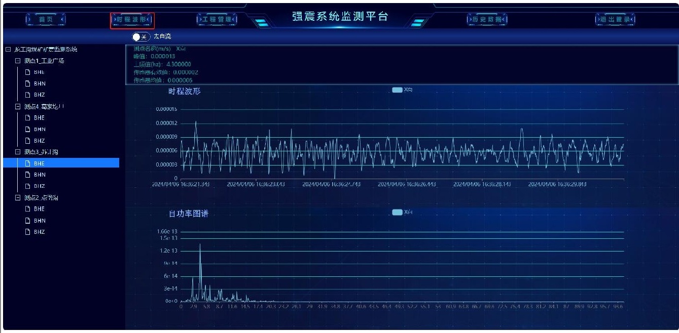
Vibration waveform and spectrum output
Time-history waveform and frequency results support ground vibration review, event reporting, and engineering threshold checks.
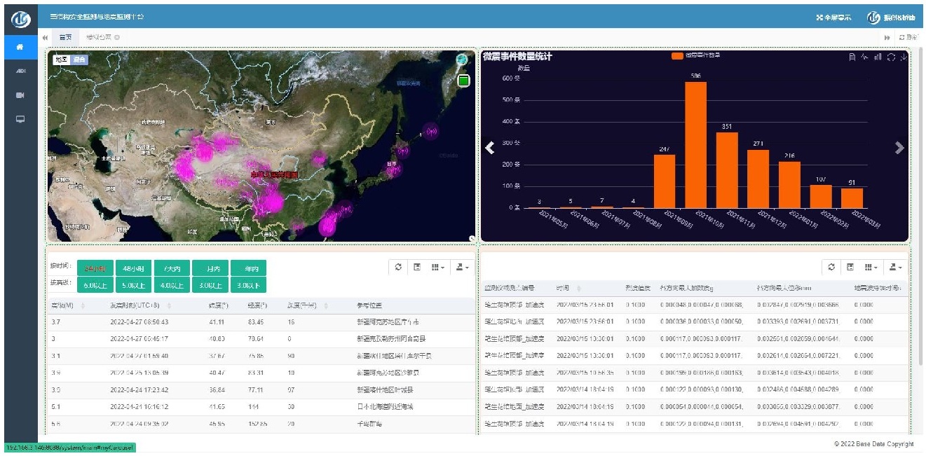
Web platform dashboard
Map, event list, and chart views help safety teams review distributed monitoring points and abnormal vibration events.
Warning platform trend view
Trend screens support long-term deformation, vibration, and alarm review across monitored engineering assets.
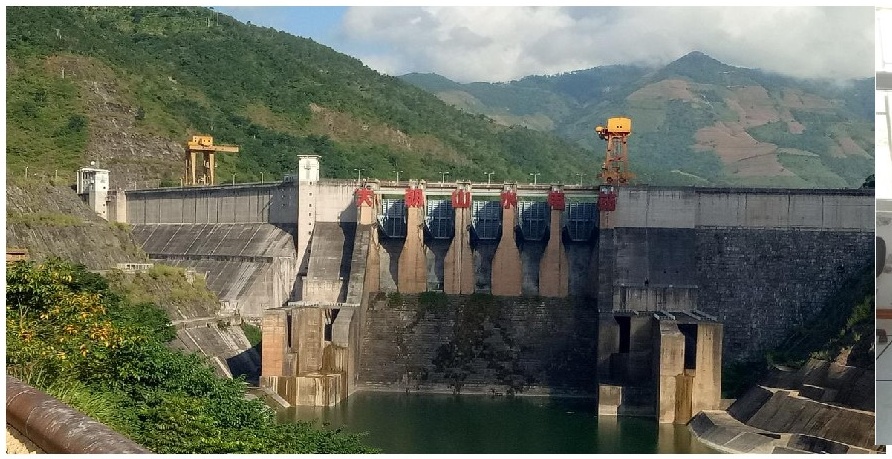
Field site monitoring environment
A dam and slope-side field environment provides a practical reference for rugged outdoor geotechnical monitoring deployments.
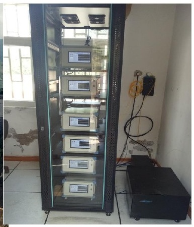
Field cabinet and acquisition equipment
Protected cabinets house acquisition and communication equipment for long-term site monitoring.
Sensor Deployment
Sensor layout and measurement purpose
Ground vibration points
DL-VIB vibration monitoring instruments
Capture ground vibration events, peak vibration values, and time-history records
Slope surface stations
DL-GN and DL-SEN displacement or tilt sensors
Track slope movement, surface deformation, and long-term stability trends
Borehole arrays
DL-SEN deep displacement monitoring points
Measure subsurface movement by depth for geotechnical interpretation
Monitoring center
DL-SYS-001
Review event records, trend alarms, and geotechnical risk reports
Data Analysis Results
Monitoring indicators and interpretation
Ground vibration
event-triggered vibration records
Safety teams could evaluate ground vibration response against engineering thresholds.
Slope movement
surface and subsurface deformation trends
Long-term movement evidence supported slope stability review.
Deep displacement
borehole movement profile
Depth-based movement data helped distinguish shallow disturbance from deeper geotechnical deformation.
Engineering Credibility
Reliability, topology, and project validation
99.98%
target data availability
IP67/68
field protection classes
4G/Fiber
site transmission options
RFQ
project-based configuration
Measurement planning
Monitoring object, measurement range, sampling rate, and signal type guide project configuration.
Communication options
DL systems support project configurations using wired, wireless, GNSS, and gateway-based communication methods.
Documentation support
Datasheets and technical selection information are available upon request for RFQ preparation.
Product selection should be confirmed against site conditions, measurement points, installation environment, and expected data output.
Structured RFQ Path
Request path for Civil Infrastructure Structural Monitoring Project
Step 1
Define Data Nodes
Sensor, wireless node, GNSS station, seismic unit, or DAQ field layer.
Step 2
Configure Network
Civil infrastructure, industrial equipment, heritage, seismic, or research monitoring chain.
Step 3
Build RFQ Scope
Asset type, measurement points, channels, sampling rate, communication, environment, and duration.
Step 4
Review Proposal
Receive system architecture, product configuration, data output, and engineering review structure.
Project Overview
Engineering context and monitoring scope
Mining and slope projects require measurable evidence of ground vibration, subsurface movement, and long-term deformation. Source materials describe ground vibration monitoring, post-blasting deformation monitoring, slope monitoring, and deep displacement applications where field sensors, rugged acquisition, and remote platform review are combined for risk control.
Client type
Mining owner, geotechnical safety team, and construction monitoring contractor
System scale
ground vibration monitoring points, slope deformation stations, and borehole displacement arrays
Project type
Civil Infrastructure Structural Monitoring