
Dam and Urban Structural Response Monitoring
A seismic monitoring case group covering dam strong-motion arrays, earthquake intensity review, automatic event reports, GNSS deformation logic, and remote network transmission.
Project Type
Civil Infrastructure Structural Monitoring
System Scale
dam strong-motion arrays, free-field stations, remote transmission, and city-level seismic data review
Data Output
earthquake event waveform, intensity, peak acceleration, displacement, duration, station status, GNSS deformation trend, and automatic reports
Engineering Value
How the system supported engineering decisions
The case strengthens DL-SE positioning without adding any new public product family.
Dam strong-motion monitoring and city seismic network workflows are expressed as event detection, reporting, and remote station management capabilities.
GNSS plus acceleration context supports broader seismic and deformation safety interpretation.
Monitoring Content
Monitoring scope and field constraints addressed by the deployment
Dam structures required measurement points at crest, gallery, foundation, free-field, and key structural sections.
Earthquake events required automatic trigger, event file storage, intensity calculation, peak acceleration review, displacement calculation, and report generation.
Remote station networks needed reliable timing, data transmission, station health review, and integration with GNSS or deformation monitoring logic.
System Configuration
Configured system architecture and data path
Field Devices
DL-VIB strong-motion and seismic instruments, DL-GN displacement stations, and field timing or communication devices
Communication Layer
Ethernet, fiber, 4G, or station network transmission from dam and free-field points to the monitoring center
Central Platform
DL seismic monitoring platform for event trigger, waveform review, automatic reports, alarms, and station health management
Case Visual Evidence
Source visuals and deployment references
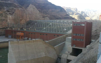
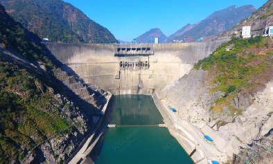
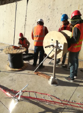
Hydropower station field site
The monitoring system is deployed around dam galleries, plant structures, and protected field stations where event data is transmitted back to the monitoring center.
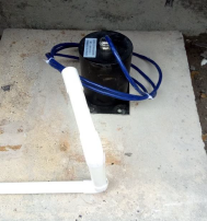
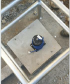
Strong-motion sensor mounted on concrete base
A protected accelerometer installation captures structural response at dam or gallery measurement points.
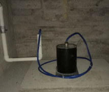
Triaxial force-balance accelerometer station
Three-component acceleration measurement supports earthquake waveform, peak acceleration, displacement, and duration analysis.
Protected free-field or reference station
Field stations provide reference ground motion data for comparison with dam crest, gallery, foundation, and structural response points.
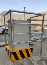
Outdoor protection frame for field instrumentation
Protective rails and barriers keep outdoor seismic instruments and cabling stable in exposed hydropower station environments.
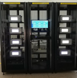
Monitoring center acquisition racks
Centralized racks receive multi-point strong-motion data and support event trigger, station status review, alarm delivery, and report generation.
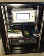
Cabinet-mounted data acquisition unit
Rack-mounted acquisition equipment links field accelerometers to the engineering seismic monitoring platform.
On-site installation inside dam structure
Gallery-side installation work covers sensor fixing, cable routing, and protected wiring for long-term strong-motion monitoring.
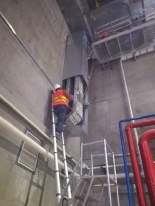
Cable routing in gallery and service area
Vertical routing and protected conduits connect structural measurement points to acquisition cabinets and the monitoring center.
Sensor Deployment
Sensor layout and measurement purpose
Dam crest and galleries
DL-VIB strong-motion instruments
Capture structural response at dam crest, downstream face, gallery, and key elevations
Free-field reference station
DL-VIB seismic monitoring instruments
Record input ground motion for structural response comparison
GNSS or deformation stations
DL-GN displacement systems
Provide deformation trend context for seismic safety review
Seismic monitoring center
DL-SYS-001
Receive remote data, identify events, generate reports, and distribute alarms
Data Analysis Results
Monitoring indicators and interpretation
Strong-motion array
multi-point dam response records
Operators could compare crest, gallery, foundation, and free-field motion during seismic events.
Event reporting
automatic earthquake report workflow
Triggered records supported rapid review of intensity, peak acceleration, displacement, and duration.
Network transmission
remote station data centralized
Monitoring teams could review station state, event data, and long-term trends from one platform.
Engineering Credibility
Reliability, topology, and project validation
99.98%
target data availability
IP67/68
field protection classes
4G/Fiber
site transmission options
RFQ
project-based configuration
Measurement planning
Monitoring object, measurement range, sampling rate, and signal type guide project configuration.
Communication options
DL systems support project configurations using wired, wireless, GNSS, and gateway-based communication methods.
Documentation support
Datasheets and technical selection information are available upon request for RFQ preparation.
Product selection should be confirmed against site conditions, measurement points, installation environment, and expected data output.
Structured RFQ Path
Request path for Civil Infrastructure Structural Monitoring Project
Step 1
Define Data Nodes
Sensor, wireless node, GNSS station, seismic unit, or DAQ field layer.
Step 2
Configure Network
Civil infrastructure, industrial equipment, heritage, seismic, or research monitoring chain.
Step 3
Build RFQ Scope
Asset type, measurement points, channels, sampling rate, communication, environment, and duration.
Step 4
Review Proposal
Receive system architecture, product configuration, data output, and engineering review structure.
Project Overview
Engineering context and monitoring scope
Dam and urban seismic projects require synchronized strong-motion data, free-field reference points, event-triggered records, and automatic engineering reports after earthquake events. Source deployments include hydropower dams with six to fourteen strong-motion points, reservoir and hydropower station monitoring, and city network style remote transmission workflows.
Client type
Dam owner, earthquake monitoring authority, and infrastructure safety team
System scale
dam strong-motion arrays, free-field stations, remote transmission, and city-level seismic data review
Project type
Civil Infrastructure Structural Monitoring