
Wind Farm Tower, Foundation, and Flange Monitoring
A structural monitoring case group covering tower vibration, foundation response, rotating-structure vibration trends, flange gap change, bolt loosening risk, and severe-weather condition monitoring.
Project Type
Civil Infrastructure Structural Monitoring
System Scale
wind turbine towers, foundations, substations, and severe-weather monitoring points
Data Output
tower vibration, tilt, dynamic strain, flange gap trend, bolt loosening indicators, foundation response, environmental data, and alarm records
Engineering Value
How the system supported engineering decisions
The case converts wind turbine tower, foundation, blade, flange, and bolt indicators into one DL wind monitoring architecture.
Severe-weather environmental loading is expressed as an engineering RFQ input rather than an isolated product parameter.
AI risk evaluation and digital twin review support maintenance planning across wind farm assets.
Monitoring Content
Monitoring scope and field constraints addressed by the deployment
Wind turbine towers and foundations required synchronized vibration, tilt, strain, and environmental response monitoring under severe wind loading.
Flange and bolt risk needed trend recognition from gap change, vibration features, and historical response rather than manual inspection only.
Wind farm owners needed remote transmission, automatic brief generation, and AI-based risk evaluation for maintenance planning.
System Configuration
Configured system architecture and data path
Field Devices
DL-SEN vibration, tilt, strain, crack, and environmental sensing points installed on wind tower, foundation, flange, and blade-related positions
Communication Layer
DL-DAQ distributed acquisition with protected field cabinets and remote transmission to the monitoring center
Central Platform
DL-SHM platform for waveform review, trend storage, risk evaluation, digital twin display, and maintenance brief output
Case Visual Evidence
Source visuals and deployment references
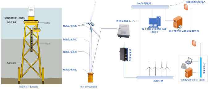
Wind turbine monitoring network
Turbine sensors, local acquisition, central station, and remote diagnosis workflow.
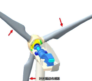
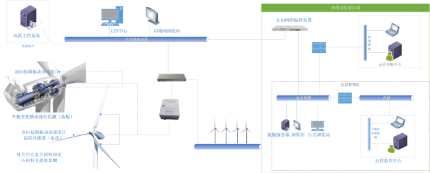
Blade and nacelle monitoring detail
Blade vibration, rotating structure, and nacelle-side measurement points.
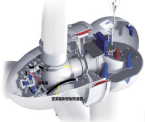
Nacelle internal sensor layout
Monitoring arrangement for nacelle and drivetrain-related structural response.
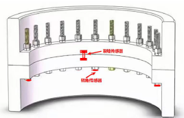
Flange and bolt loosening monitoring
Flange gap and bolt-related monitoring points for looseness trend review.
Monitoring Platform Screens
Wind farm overview, trend analysis, and alarm status
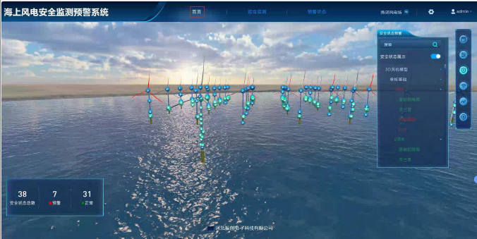
3D wind farm overview
Wind farm asset status, turbine distribution, and safety points are presented in one operating view.
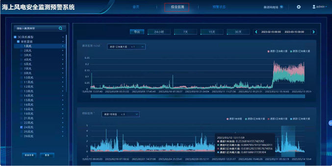
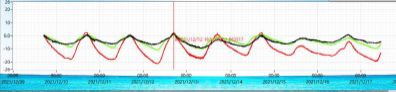
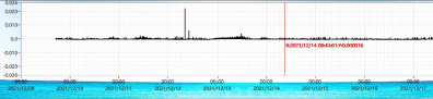
Integrated trend dashboard
Long-term trend curves support condition review and abnormal operating-condition analysis.
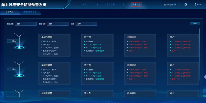
Alarm and status panel
Turbine-level foundation, flange, vibration, and blade status are grouped for maintenance review.
Sensor Deployment
Sensor layout and measurement purpose
Tower and foundation
DL-SEN acceleration, tilt, and strain sensors
Measure tower vibration, tower posture, foundation response, and dynamic strain under operating conditions
Flange and bolt sections
DL-SEN crack, angle, and vibration sensing points
Track flange gap trends, bolt loosening risk, and local vibration feature change
Wind farm field station
DL-DAQ systems
Synchronize tower, foundation, blade, flange, and environmental channels
Monitoring center
DL-SYS-001
Provide remote display, AI risk evaluation, digital twin review, and maintenance reports
Data Analysis Results
Monitoring indicators and interpretation
Tower vibration and tilt
operating-condition response trends
Maintenance teams could correlate tower response with wind and severe-weather conditions.
Flange and bolt risk
gap, angle, and vibration features reviewed together
The workflow supported loosening trend recognition before severe structural risk.
Wind farm monitoring coverage
Multiple wind farm asset types represented
The case validates wind monitoring as a repeatable SHM scenario.
Engineering Credibility
Reliability, topology, and project validation
99.98%
target data availability
IP67/68
field protection classes
4G/Fiber
site transmission options
RFQ
project-based configuration
Measurement planning
Monitoring object, measurement range, sampling rate, and signal type guide project configuration.
Communication options
DL systems support project configurations using wired, wireless, GNSS, and gateway-based communication methods.
Documentation support
Datasheets and technical selection information are available upon request for RFQ preparation.
Product selection should be confirmed against site conditions, measurement points, installation environment, and expected data output.
Structured RFQ Path
Request path for Civil Infrastructure Structural Monitoring Project
Step 1
Define Data Nodes
Sensor, wireless node, GNSS station, seismic unit, or DAQ field layer.
Step 2
Configure Network
Civil infrastructure, industrial equipment, heritage, seismic, or research monitoring chain.
Step 3
Build RFQ Scope
Asset type, measurement points, channels, sampling rate, communication, environment, and duration.
Step 4
Review Proposal
Receive system architecture, product configuration, data output, and engineering review structure.
Project Overview
Engineering context and monitoring scope
Wind farms required long-term safety evidence for tower and foundation behavior under wind and severe-weather conditions. Source deployments covered multiple wind farm projects, with monitoring focused on tower vibration, tilt, dynamic strain, flange gap, and online risk evaluation.
Client type
Wind farm owner, design institute, and maintenance team
System scale
wind turbine towers, foundations, substations, and severe-weather monitoring points
Project type
Civil Infrastructure Structural Monitoring